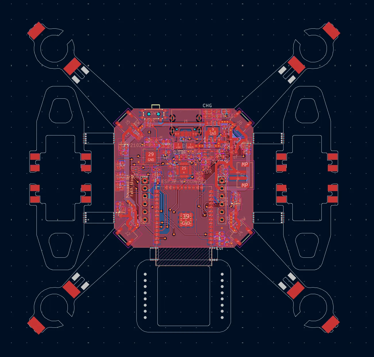
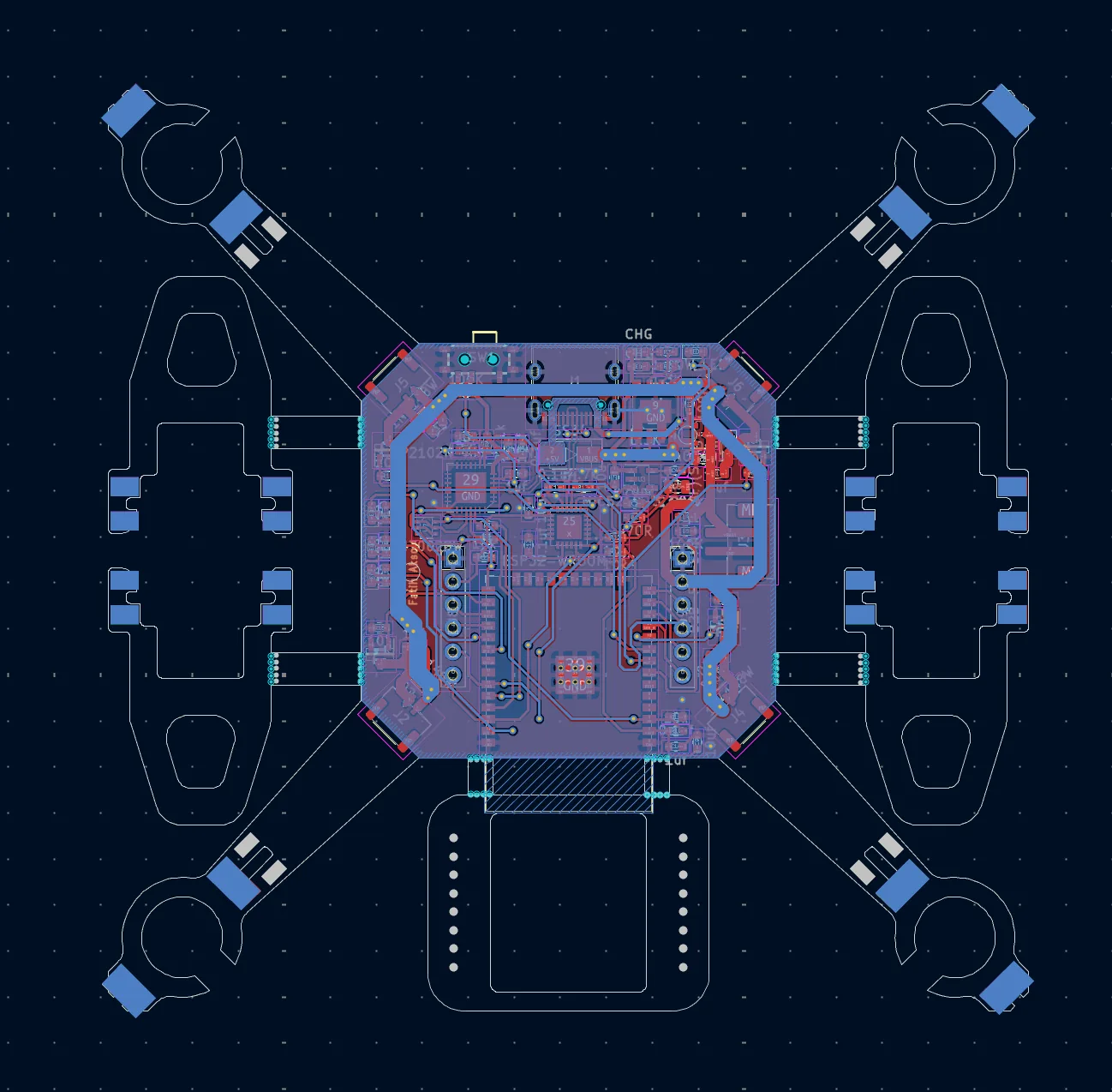
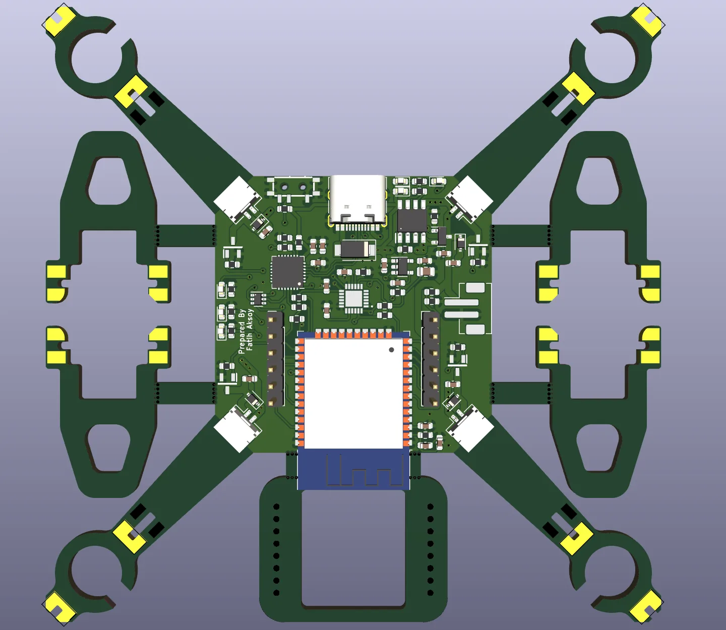
The goal was to design a flight controller from scratch instead of buying one, solving power, sensing and motor drive on a single board. The board's arms are also the frame: the motors sit in the mounts at the ends of the arms.
The ESP32's two cores split the work: one runs sensor reads and the PID loop, the other handles communication with the ground station.
05.2Block diagram
05.3Hardware
MCU
ESP32-WROOM-32 (dual-core, 240 MHz)
IMU
MPU-6050 · I²C (SDA IO21, SCL IO22)
Motor drive
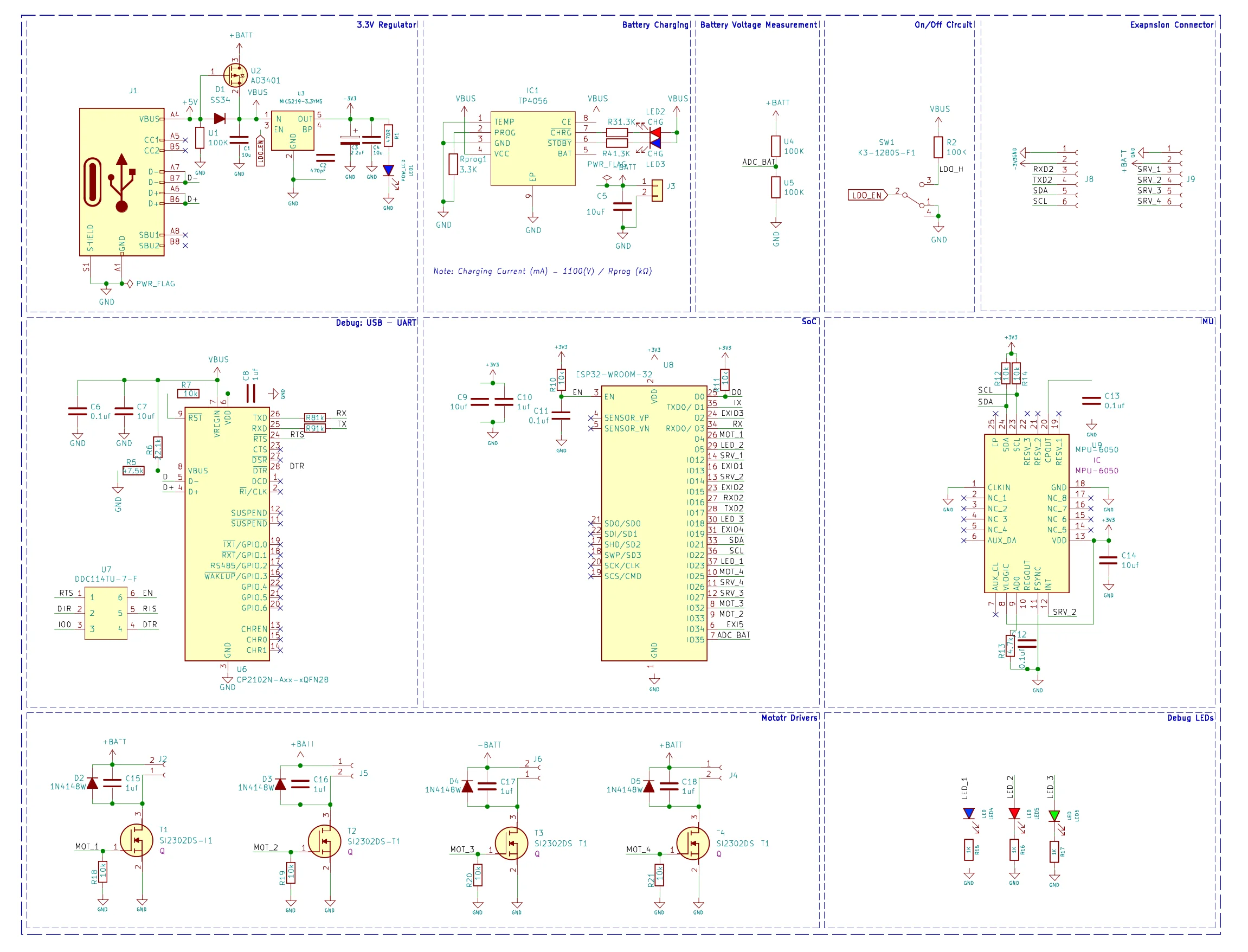
4 × SI2302 N-MOSFET, low-side; 1N4148W flyback diode and 1 µF capacitor on each motor
Motor pins
MOT_1 IO4 · MOT_2 IO33 · MOT_3 IO32 · MOT_4 IO25
Power
1S Li-Po; charged from USB-C via TP4056; MIC5219 3.3 V LDO; AO3401 for USB/battery path selection
Programming
CP2102N USB-UART with auto reset/boot circuit
Other
Battery voltage sense (IO35), on/off circuit, 3 debug LEDs, expansion header (UART2, I²C)
Fig. 1Schematic — KiCad schematic: regulator, charger, USB-UART, SoC, IMU and motor drivers.
Fig. 2PCB, top layer — Layout with the top copper layer in front; arms and motor mounts are part of the PCB.Fig. 3PCB, bottom layer — Layout with the bottom copper layer in front.Fig. 43D view — Top-down KiCad 3D view of the board.
05.4Software
Core 0: MPU-6050 reads, accelerometer/gyro fusion with a complementary filter, roll/pitch/yaw PID loop.
Core 1: control input and telemetry over ESP-NOW (or UDP over Wi-Fi).
05.5Status
Schematic and PCB design
PID stabilisation and complementary filter
GPS-based autonomous waypoint following (in development)